Kad antara muka rangkaian
Daripada Wikipedia, ensiklopedia
bebas.

Kad kawalan antara muka
rangkaianEthernet yang menyambungkan papan
induk melalui bas ISA yang kini lapuk.
Kad antara muka rangkaian merupakan satu peranti yang
digunakan oleh komputer untuk berkomunikasi di
dalam rangkaian. Ia bertindak sebagai antara muka fizikal atau penyambung di
antara komputer anda dengan kabel rangkaian. Antara muka rangkaian ini ada yang
berbentuk kad dan ada yang berupa komponen dalam papan induk komputer.
Kad rangkaian ini juga
menerima data input dari kabel dan menterjemahkannya kepada byte yang difahami oleh unit pemprosesan pusat komputer. Kad rangkaian
mengandungi perkakasan dan program firmware (aturcara rutin yang
tersimpan dan ROM) yang mengimplemen fungsi-fungsilogikal link control (LLC) dan media access control (MAC) pada lapisan pautan
data model OSI.
Fungsi
Fungsi kad antara muka
rangkaian ialah:
§ Menyediakan data dari
komputer untuk kabel rangkaian
§ Menghantar data ke komputer
yang lain
§ Mengawal aliran data di
antara komputer dan sistem kabel penyambung
Penyediaan data
Sebelum data dalam
rangkaian boleh dihantar ke destinasi tertentu, kad rangkaian perlu
menukarkannya kepada bentuk yang boleh bergerak dalam kabel rangkaian.
Dalam kabel rangkaian, data
bergerak dalam rentetan bit tunggal. Apabila data bergerak dalam kabel
rangkaian ia dikatakan bergerak sebagai transmisi siri kerana satu bit yang
bergerak akan diekori oleh bit yang lain. Dengan kata lain kabel ini merupakan
laluan sehala. Data dalam laluan ini sentiasa bergerak dalam satu arah sahaja
iaitu sama ada ia menghantar atau menerima data.
Kad rangkaian mengambil
data yang bergerak secara selari dalam satu kelompok dan menstrukturkannya
semula supaya ia boleh dialirkan melalui laluan siri 1-bit pada kabel
rangkaian. Ini boleh dilaksanakan dengan menterjemahkan isyarat digital
komputer kepada isyarat yang boleh bergerak dalam kabel rangkaian iaitu isyarat
elektrik dan isyarat optik. Komponen yang bertanggungjawab menukarkan bentuk
isyarat ini dikenali sebagai tranceiver (transmitter/receiver).
Wireless
network interface controller
From Wikipedia, the free
encyclopedia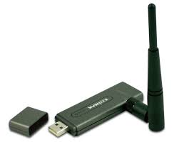


Modes of operation
§ A1 A2 IEEE
802.11y-2008 extended
operation of 802.11a to the licensed 3.7 GHz band. Increased power limits
allow a range up to 5,000 m. As of 2009, it is only being licensed in the
United States by the FCC.
Wireless
network interface controller
Modes of operation
Infrastructure mode
In an infrastructure mode network the WNIC
needs a wireless access
point: all data is transferred using the access point as the central
hub. All wireless nodes in an infrastructure mode network
connect to an access point. All nodes connecting to the access point must have
the same service set
identifier (SSID) as
the access point, and if the access point is enabled with WEP they
must have the same WEP key or other authentication parameters.
Ad-hoc mode
In an ad-hoc mode network the WNIC does not
require an access point, but rather can directly interface with all other
wireless nodes directly. All the nodes in an ad-hoc network must have the
same channel and
SSID.
Specifications
WNICs are designed around the IEEE 802.11 standard which sets out low-level
specifications for how all wireless networks operate. Earlier interface controllers
are usually only compatible with earlier variants of the standard, while newer
cards support both current and old standards.
Specifications commonly used in marketing
materials for WNICs include:
§ Wireless data transfer rates (measured in Mbit/s); these
range from 2 Mbit/s to 54 Mbit/s.[4]
§ Wireless transmit power (measured in dBm)
§ Wireless network standards (may include standards such as 802.11b, 802.11g, 802.11n, etc.) 802.11g offers data transfer
speeds equivalent to 802.11a – up to 54 Mbit/s – and the wider 300-foot
(91 m) range of 802.11b, and is backward compatible with 802.11b.
Most Bluetooth cards do not implement any
form of the 802.11 standard.
Range
Wireless range may be substantially affected
by objects in the way of the signal and by the quality of the antenna. Large
electrical appliances, such as refrigerators, fuse boxes, metal plumbing, and
air conditioning units can impede a wireless network signal. The theoretical
maximum range of Wi-Fi is only reached under ideal circumstances and true effective
range is typically about half of the theoretical range.[4] Specifically, the maximum throughput
speed is only achieved at extremely close range (less than 25 feet (7.6 m)
or so); at the outer reaches of a device's effective range, speed may decrease
to around 1 Mbit/s before it drops out altogether. The reason is that wireless
devices dynamically negotiate the top speed at which they can communicate
without dropping too many data packets.
Ethernet hub
From Wikipedia, the free
encyclopedia
Ethernet hub
From Wikipedia, the free
encyclopedia
4-port Ethernet hub
An Ethernet hub, active hub, network hub, repeater hub, multiport repeateror hub is a device for connecting
multiple Ethernet devices together and making
them act as a single network segment. It
has multiple input/output (I/O) ports, in which a signal introduced at the input of
any port appears at the output of
every port except the original incoming. A hub works at the physical layer (layer 1) of the OSI model.[1] The device is a form of
multiport repeater. Repeater hubs also participate in collision detection,
forwarding a jam signal to all ports if it detects
a collision.
Some hubs may also come with a BNC and/or Attachment Unit Interface (AUI) connector to allow
connection to legacy 10BASE2 or 10BASE5 network segments. The
availability of low-priced network switches has largely rendered hubs
obsolete but they are still seen in 20th century installations and more
specialized applications.
Technical information
A network hub is an unsophisticated device in
comparison with, for example, a switch. A hub does
not examine or manage any of the traffic that comes through it: any packet entering
any port is rebroadcast on all other ports.[2] Effectively, it is barely
aware of frames or packets and mostly operates on raw bits. Consequently,
packet collisions are more frequent in networks connected using hubs than in
networks connected using more sophisticated devices.[1]
100 Mbit/s hubs and repeaters come in two
different speed grades: Class I delay the signal for a maximum of 140 bit times
(enabling translation between 100Base-TX, 100Base-FX and 100Base-T4) and Class
II hubs delay the signal for a maximum of 92 bit times (enabling installation
of two hubs in a single collision domain).[3]
The need for hosts to be able to detect
collisions limits the number of hubs and the total size of a network built
using hubs (a network built using switches does not have these
limitations). For 10 Mbit/s networks built using repeater hubs, the 5-4-3 rule must be followed: up to 5
segments (4 hubs) are allowed between any two end stations.[2] For 10BASE-T networks, up
to five segments and four repeaters are allowed between any two hosts.[4] For 100 Mbit/s
networks, the limit is reduced to 3 segments (2 hubs) between any two end
stations, and even that is only allowed if the hubs are of Class II. Some hubs
have manufacturer specific stack ports allowing them to be combined in a way
that allows more hubs than simple chaining through Ethernet cables, but even
so, a large fast Ethernet network is likely to
require switches to avoid the chaining limits of hubs.[1]
Most hubs detect typical problems, such as
excessive collisions and jabbering on individual ports, and partition the port, disconnecting it
from the shared medium. Thus, hub-based twisted-pair Ethernet is generally more
robust than coaxial cable-based Ethernet (e.g. 10BASE2), where a misbehaving
device can adversely affect the entire collision domain.[2] Even if not partitioned
automatically, a hub simplifies troubleshooting because hubs remove the need to
troubleshoot faults on a long cable with multiple taps; status lights on the
hub can indicate the possible problem source or, as a last resort, devices can
be disconnected from a hub one at a time much more easily than from a coaxial
cable.
Hubs are classified as physical layer devices
in the OSI model. At the physical layer, hubs support little in the way of
sophisticated networking. Hubs do not read any of the data passing through them
and are not aware of their source or destination addressing. A hub simply
receives incoming Ethernet frames,
regenerates the electrical signal on the bit (more precisely the symbol) level, and
broadcasts these symbols out to all other devices on the network.[1]
To pass data through the repeater in a usable
fashion from one segment to the next, the framing and data rate must be the
same on each segment. This means that a repeater cannot connect an 802.3
segment (Ethernet) and an 802.5 segment (Token Ring) or a 10 MBit/s
segment to 100 MBit/s Ethernet.
Dual-speed hub
In the early days of fast Ethernet, Ethernet
switches were relatively expensive devices. Hubs suffered from the problem that
if there were any10BASE-T devices connected then the
whole network needed to run at 10 Mbit/s. Therefore a compromise between a
hub and a switch was developed, known as a dual-speed hub. These devices consisted
of an internal two-port switch, dividing the 10 Mbit/s and 100 Mbit/s
segments. The device would typically consist of more than two physical ports.
When a network device becomes active on any of the physical ports, the device
attaches it to either the 10 Mbit/s segment or the 100 Mbit/s
segment, as appropriate. This prevented the need for an all-or-nothing
migration fast Ethernet networks. These devices are considered hubs because the
traffic between devices connected at the same speed is not switched.
Uses
Historically, the main reason for purchasing
hubs rather than switches was their price. This motivator has largely been
eliminated by reductions in the price of switches, but hubs can still be useful
in special circumstances:
§ For inserting a protocol analyzer into a network connection,
a hub is an alternative to a network tap or port mirroring.[5]
§ When a switch is accessible
for end users to make connections, for example, in a conference room, an
inexperienced or careless user (orsaboteur) can bring
down the network by connecting two ports together, causing a loop. This can be
prevented by using a hub, where a loop will break other users on the hub, but
not the rest of the network. This hazard can also be avoided by using switches
that can detect and deal with loops, for example by implementing the spanning tree protocol.
§ A hub with a 10BASE2 port
can be used to connect devices that only support 10BASE2 to a modern network.
The same goes for linking in an old 10BASE5 network segment using an AUI port
on a hub. Individual devices that were intended for thicknet can also be linked
to modern Ethernet by using an AUI-10BASE-T transceiver.
Router
(computing)
From Wikipedia, the free
encyclopedia

A Cisco ASM/2-32EM router deployed atCERN in
1987
A router is a device that forwards data packets between computer networks,
creating an overlayinternetwork.
A router is connected to two or more data lines from
different networks. When a data packet comes in on one of the lines, the router
reads the address information in the packet to determine its ultimate
destination. Then, using information in its routing table or routing policy, it
directs the packet to the next network on its journey. Routers perform the
"traffic directing" functions on the Internet. A data packet is typically forwarded
from one router to another through the networks that constitute the
internetwork until it gets to its destination node.[1]
The most familiar type of routers are home and small office routers that simply pass data, such as web
pages and email, between the home computers and the owner's cable or DSL modem, which
connects to the Internet through an ISP. However more sophisticated routers range
from enterprise routers, which connect large business or ISP networks up to the
powerful core routers that forward data at high speed along
the optical fiber lines of the Internet backbone.
Applications
When multiple routers are used in
interconnected networks, the routers exchange information about destination
addresses, using a dynamic routing protocol. Each router builds up a table
listing the preferred routes between any two systems on the interconnected
networks. A router has interfaces for different physical types of network
connections, (such as copper cables, fiber optic, or wireless transmission). It
also contains firmware for
different networking protocol standards.
Each network interface uses this specialized computer software to enable data
packets to be forwarded from one protocol transmission system to another.
Routers may also be used to connect two or
more logical groups of computer devices known as subnets, each with a
different sub-network address.
The subnets addresses recorded in the router do not necessarily map directly to
the physical interface connections.[2] A router has two stages of operation
called planes:[3]
§ Control plane:
A router records a routing table listing what route should be used to forward a
data packet, and through which physical interface connection. It does this
using internal pre-configured addresses, called static routes.

A typical home or small office router showing the ADSL telephone
line andEthernet network cable connections
§ Forwarding plane:
The router forwards data packets between incoming and outgoing interface
connections. It routes it to the correct network type using information that
the packet headercontains. It uses data recorded in the
routing table control plane.
Routers may provide connectivity within
enterprises, between enterprises and the Internet, and between internet service providers (ISPs) networks. The largest routers
(such as the Cisco CRS-1or Juniper T1600) interconnect the
various ISPs, or may be used in large enterprise networks.[4]Smaller
routers usually provide connectivity for typical home and office networks.
Other networking solutions may be provided by a backbone Wireless Distribution System (WDS), which avoids the costs of
introducing networking cables into buildings.
All sizes of routers may be found inside enterprises.[5] The most powerful routers are usually found in ISPs, academic and research facilities. Large businesses may also need more powerful routers to cope with ever increasing demands of intranet data traffic. A three-layer model is in common use, not all of which need be present in smaller networks.[6]
Access
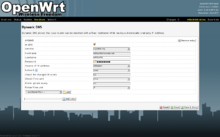
A screenshot of the LuCI web interface used by OpenWrt. This page configuresDynamic DNS.
Access routers, including 'small office/home
office' (SOHO) models, are located at customer sites such as branch offices
that do not need hierarchical
routing of their own.
Typically, they are optimized for low cost. Some SOHO routers are capable of
running alternative free Linux-based firmwares like Tomato, OpenWrt or DD-WRT.[7]
Distribution
Distribution routers aggregate traffic from
multiple access routers, either at the same site, or to collect the data
streams from multiple sites to a major enterprise location. Distribution
routers are often responsible for enforcing quality of service across a WAN, so they may have
considerable memory installed, multiple WAN interface connections, and
substantial onboard data processing routines. They may also provide connectivity
to groups of file servers or other external networks.
Security
External networks must be carefully
considered as part of the overall security strategy. Separate from the router
may be a firewall or VPNhandling device, or the router may include
these and other security functions. Many companies produced security-oriented
routers, including Cisco Systems' PIX and ASA5500 series, Juniper's Netscreen,
Watchguard's Firebox, Barracuda's variety of mail-oriented devices, and many
others.
Core
In enterprises, a core router may provide a "collapsed
backbone" interconnecting the distribution tier routers from multiple
buildings of a campus, or large enterprise locations. They tend to be optimized
for high bandwidth.[8]
Internet connectivity and internal use
Routers intended for ISP and
major enterprise connectivity usually exchange routing information using the Border Gateway Protocol (BGP).RFC 4098[9] standard defines the types of
BGP-protocol routers according to the routers' functions:
§ Edge router: Also
called a Provider Edge router, is placed at the edge of an ISP network. The
router uses External BGP to
EBGP protocol routers in other ISPs, or a large enterprise Autonomous System.
§ Subscriber edge router: Also called a Customer Edge router, is located at the edge of the
subscriber's network, it also uses EBGP protocol to its provider's Autonomous
System. It is typically used in an (enterprise) organization.
§ Inter-provider border router: Interconnecting ISPs, is a BGP-protocol router that maintains BGP
sessions with other BGP protocol routers in ISP Autonomous Systems.
§ Core router:
A core router resides within an Autonomous System as
a back bone to carry traffic between edge routers.[10]
§ Within an ISP: In the ISPs Autonomous System, a router
uses internal BGP protocol to communicate with other ISP edge routers, otherintranet core
routers, or the ISPs intranet provider border routers.
§ "Internet backbone:" The Internet no longer has
a clearly identifiable backbone, unlike its predecessor networks. See default-free zone(DFZ).
The major ISPs system routers make up what could be considered to be the
current Internet backbone core.[11] ISPs operate all four types of the
BGP-protocol routers described here. An ISP "core" router is used to
interconnect its edge and border routers. Core routers may also have
specialized functions in virtual private networks based on a combination of BGP and Multi-Protocol Label Switchingprotocols.[12]
§ Port forwarding: Routers are also used for port forwarding between private internet connected
servers.[5]
§ Voice/Data/Fax/Video Processing Routers: Commonly
referred to as access servers or gateways, these devices
are used to route and process voice, data, video, and fax traffic on the
internet. Since 2005, most long-distance phone calls have been processed as IP traffic (VOIP) through a voice gateway. Voice traffic
that the traditional cable networks once carried[clarification
needed]. Use of access server type routers expanded
with the advent of the internet, first with dial-up access, and another
resurgence with voice phone service.
Historical and technical information

Avaya ERS 8600 (2010)
The very first device that had fundamentally
the same functionality as a router does today, was theInterface Message Processor (IMP); IMPs were the devices that made
up the ARPANET, the firstpacket network. The idea for a router (called
"gateways" at the time) initially came
about through an international group of computer networking researchers called
the International Network Working Group (INWG). Set up in 1972 as an informal
group to consider the technical issues involved in connecting different
networks, later that year it became a subcommittee of theInternational Federation for Information Processing.[13]
These devices were different from most
previous packet networks in two ways. First, they connected dissimilar kinds of
networks, such as serial lines and local area
networks. Second, they were connectionless devices, which had no role in assuring
that traffic was delivered reliably, leaving that entirely to the hosts (this particular idea had been
previously pioneered in theCYCLADES network).
The idea was explored in more detail, with
the intention to produce a prototype system, as part of two contemporaneous
programs. One was the initial DARPA-initiated program, which created theTCP/IP architecture
in use today.[14] The other was a program at Xerox PARC to explore new networking
technologies, which produced the PARC Universal
Packet system, due to
corporate intellectual property concerns it received little attention outside
Xerox for years.[15]
Some time after early 1974 the first Xerox
routers became operational. The first true IP router was developed by Virginia
Strazisar at BBN, as part of that
DARPA-initiated effort, during 1975-1976. By the end of 1976, three PDP-11-based routers were in service in the
experimental prototype Internet.[16]
The first multiprotocol routers were
independently created by staff researchers at MIT and Stanfordin
1981; the Stanford router was done by William Yeager, and the
MIT one by Noel Chiappa; both were also based on PDP-11s.[17][18][19][20]
Virtually all networking now uses TCP/IP, but
multiprotocol routers are still manufactured. They were important in the early
stages of the growth of computer networking, when protocols other than TCP/IP
were in use. Modern Internet routers that handle both IPv4 and IPv6 are
multiprotocol, but are simpler devices than routers processing AppleTalk,
DECnet, IP, and Xerox protocols.
From the mid-1970s and in the 1980s,
general-purpose mini-computers served as routers. Modern high-speed
routers are highly specialized computers with extra hardware added to speed
both common routing functions, such as packet forwarding, and specialised
functions such as IPsecencryption.
There is substantial use of Linux and Unix software
based machines, running open source routing code, for research and other
applications. Cisco's operating system was independently
designed. Major router operating systems, such as those from Juniper Networks and Extreme Networks, are
extensively modified versions of Unix software.
Forwarding
For pure Internet Protocol (IP) forwarding function, a router is
designed to minimize the state information
associated with individual packets. The main purpose of a router is to connect
multiple networks and forward packets destined either for its own networks or
other networks. A router is considered a Layer 3 device
because its primary forwarding decision is based on the information in the
Layer 3 IP packet, specifically the destination IP address. This process is
known as routing. When each router receives a packet, it searches its routing
table to find the best match between the destination IP address of the packet
and one of the network addresses in the routing table. Once a match is found,
the packet is encapsulated in the Layer 2 data
link frame for that outgoing interface. A router does not look into the actual
data contents that the packet carries, but only at the layer 3 addresses to
make a forwarding decision, plus optionally other information in the header for
hint on, for example, QoS. Once a packet is forwarded, the router does not
retain any historical information about the packet, but the forwarding action
can be collected into the statistical data, if so configured.
Forwarding decisions can involve decisions at
layers other than layer 3. A function that forwards based on layer 2
information is properly called a bridge. This function
is referred to as layer 2 bridging, as the addresses it uses to forward the
traffic are layer 2 addresses (e.g. MAC addresses on Ethernet).
Besides making decision as which interface a
packet is forwarded to, which is handled primarily via the routing table, a
router also has to manage congestion, when packets arrive at a rate higher than
the router can process. Three policies commonly used in the Internet are tail drop, random early
detection (RED), and weighted random early detection (WRED). Tail drop is the simplest and
most easily implemented; the router simply drops packets once the length of the
queue exceeds the size of the buffers in the router. RED probabilistically
drops datagrams early when the queue exceeds a pre-configured portion of the
buffer, until a pre-determined max, when it becomes tail drop. WRED requires a
weight on the average queue size to act upon when the traffic is about to
exceed the pre-configured size, so that short bursts will not trigger random
drops.
Another function a router performs is to
decide which packet should be processed first when multiple queues exist. This
is managed throughquality of
service (QoS), which
is critical when Voice over IP is deployed, so that delays between
packets do not exceed 150ms to maintain the quality of voice conversations.
Yet another function a router performs is
called policy-based
routing where special
rules are constructed to override the rules derived from the routing table when
a packet forwarding decision is made.
These functions may be performed through the
same internal paths that the packets travel inside the router. Some of the
functions may be performed through an application-specific integrated circuit (ASIC) to avoid overhead caused by
multiple CPU cycles, and others may have to be performed through the CPU as
these packets need special attention that cannot be handled by an ASIC.
Wireless access point.
In computer
networking, a wireless access point (WAP) is a device that
allows wireless devices to connect to a wired network using Wi-Fi,Bluetooth or related standards. The
WAP usually connects to a router (via a wired network), and
can relay data between the wireless devices (such as computers or printers) and
wired devices on the network.
Introduction

Linksys "WAP54G"
802.11g Wireless Access Point
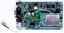
embedded RouterBoard 112 withU.FL-RSMA pigtail and R52 mini PCI Wi-Ficard widely used by wireless Internetservice
providers (WISPs) across the world
Prior to wireless networks,
setting up a computer network in a business, home or school often required
running many cables through walls and ceilings in order to deliver network
access to all of the network-enabled devices in the building. With the creation
of the Wireless Access Point, network users are now able to add devices that
access the network with few or no cables. Today's WAPs are built to support a
standard for sending and receiving data using radio frequencies rather than
cabling. Those standards, and the frequencies they use are defined by the IEEE. Most WAPs use IEEE 802.11 standards.
Common WAP applications
A typical corporate use involves attaching
several WAPs to a wired network and then providing wireless access to the
office LAN.
The wireless access points are managed by a WLAN Controllerwhich handles automatic adjustments to
RF power, channels, authentication, and security. Further, controllers can be
combined to form a wireless mobility group to allow inter-controller
roaming. The controllers can be part of a mobility domain to allow clients
access throughout large or regional office locations. This saves the clients
time and administrators overhead because it can automatically re-associate or
re-authenticate.
A hotspot is a common public
application of WAPs, where wireless clients can connect to the Internet without
regard for the particular networks to which they have attached for the moment.
The concept has become common in large cities, where a combination of
coffeehouses, libraries, as well as privately owned open access points, allow
clients to stay more or less continuously connected to the Internet, while
moving around. A collection of connected hotspots can be referred to as a lily-pad
network.
The majority of WAPs are used in Home wireless networks.[citation needed] Home networks generally
have only one WAP to connect all the computers in a home. Most are wireless routers,
meaning converged devices that include the WAP, a router,
and, often, an ethernet switch.
Many also include a broadband modem. In places where most homes have their own
WAP within range of the neighbors' WAP, it's possible for technically savvy people
to turn off their encryption and set up a wireless community network, creating an intra-city
communication network although this does not negate the requirement for a wired
network.
A WAP may also act as the network's
arbitrator, negotiating when each nearby client device can transmit. However,
the vast majority of currently installed IEEE 802.11 networks do not implement
this, using a distributed pseudo-random algorithm called CSMA/CA instead.
Wireless access point vs. ad hoc network
Some people confuse Wireless Access Points
with Wireless Ad Hoc networks. An Ad Hoc network uses a
connection between two or more devices without using a wireless access
point: the devices communicate directly when in range. An Ad Hoc network is
used in situations such as a quick data exchange or a multiplayer LAN game
because setup is easy and does not require an access point. Due to its
peer-to-peer layout, Ad Hoc connections are similar to Bluetooth ones and are generally not
recommended for a permanent installation.[citation needed]
Internet access via Ad Hoc networks,
using features like Windows' Internet Connection Sharing, may work well with a
small number of devices that are close to each other, but Ad Hoc networks don't
scale well. Internet traffic will converge to the nodes with direct internet
connection, potentially congesting these nodes. For internet-enabled nodes,
Access Points have a clear advantage, with the possibility of having multiple
access points connected by a wired LAN.
Limitations
One IEEE 802.11 WAP can typically
communicate with 30 client systems located within a radius of 103 m.[citation needed] However, the actual range
of communication can vary significantly, depending on such variables as indoor
or outdoor placement, height above ground, nearby obstructions, other
electronic devices that might actively interfere with the signal by broadcasting
on the same frequency, type ofantenna, the current weather, operating radio frequency, and
the power output of devices. Network designers can extend the range of WAPs
through the use of repeaters and reflectors, which
can bounce or amplify radio signals that
ordinarily would go un-received. In experimental conditions, wireless
networking has operated over distances of several hundred kilometers.[1]
Most jurisdictions have only a limited
number of frequencies legally available for use
by wireless networks. Usually, adjacent WAPs will use different frequencies
(Channels) to communicate with their clients in order to avoid interference between the two nearby
systems. Wireless devices can "listen" for data traffic on other
frequencies, and can rapidly switch from one frequency to another to achieve
better reception. However, the limited number of frequencies becomes
problematic in crowded downtown areas with tall buildings using multiple WAPs.
In such an environment, signal overlap becomes an issue causing interference,
which results in signal droppage and data errors.
Wireless networking lags wired networking in
terms of increasing bandwidth and throughput. While
(as of 2010) typical wireless devices for the consumer market can reach speeds
of 300 Mbit/s (megabits per second) (IEEE 802.11n) or 54
Mbit/s (IEEE 802.11g), wired
hardware of similar cost reaches 1000 Mbit/s (Gigabit Ethernet).
One impediment to increasing the speed of wireless communications comes from Wi-Fi's use of a shared communications medium,
so a WAP is only able to use somewhat less than half the actual over-the-air
rate for data throughput. Thus a typical 54 MBit/s wireless connection actually
carries TCP/IP data at 20 to 25 Mbit/s.
Users of legacy wired networks expect faster speeds, and people using wireless
connections keenly want to see the wireless networks catch up.
By 2012, 802.11n based access points and
client devices have already taken a fair share of the marketplace and with the finalization of the 802.11n
standard in 2009 inherent problems
integrating products from different vendors are less prevalent.
Security
Wireless access has special security considerations. Many wired
networks base the security on physical access control, trusting all the users
on the local network, but if wireless access points are connected to the
network, anyone on the street or in the neighboring office could connect.
The most common solution is wireless traffic
encryption. Modern access points come with built-in encryption. The first
generation encryption scheme WEP proved easy to crack; the
second and third generation schemes, WPA and WPA2, are considered
secure if a strong enoughpassword or passphrase is used.
Specialised WAPs

Industrial Wireless Access
Point
Industrial grade WAPs are rugged, with a
metal cover and a DIN rail mount. During operations
they can tolerate a wider temperature range, high humidity and exposure to
water, dust, and oil. Wireless security includes:WPA-PSK, WPA2, IEEE 802.1x/RADIUS, WDS, WEP, TKIP, and CCMP (AES) encryption. Unlike some home consumer models,
industrial wireless access points can also act as a bridge, router, or a
client.
No comments:
Post a Comment